Door de website toch te gebruiken met deze browser kan de website er anders uitzien dan bedoelt en kunnen wij de veiligheid niet garanderen
FAQ
Frequently Asked Questions
Attitude Control Systems
In space, there is nothing to hold on to. If a spacecraft needs to move or turn, it cannot simply push on something else to do so.
In order to allow spacecraft to change their orientation in a reasonable amount of time, designers have two main options at their disposal.
The most well-known from the general public is certainly the use of thrusters. Thrusters burn fuel or simply eject stored gases at high speed to produce a force. Thrusters can be very powerful, and are able to move spacecraft very fast, but have (at least) one obvious limitation. They need fuel to work, and since they are no gas stations is space yet, they end up running out.
The other option, used by the majority of satellites, is momentum exchange devices. Momentum exchange devices are a family of actuators that are based on the law of conservation of angular momentum, and can produce torques directly without requiring any fuel (except electricity). We distinguish two categories of momentum exchange devices based on how they produce torques.
Reaction wheels accelerate a flywheel to generate torques
Control Moment Gyroscopes change the direction of a spinning flywheel to generate gyroscopic torques
Although the technology differs, both categories involve the use of a flywheel, and the exchange of (angular) momentum with the spacecraft.
Technically, the accumulation of angular momentum is generated by the production of a torque for a certain period of time. As these devices do not use any fuel, and do not eject any mass or energy, the total momentum on board the satellite does not change. This means that the movement that is imparted on the satellite (and it’s momentum) is compensated for by a momentum stored in these devices. Since momentum is conserved, it is in practice always transferred from the spacecraft to these devices and vice versa, hence the name momentum exchange devices.
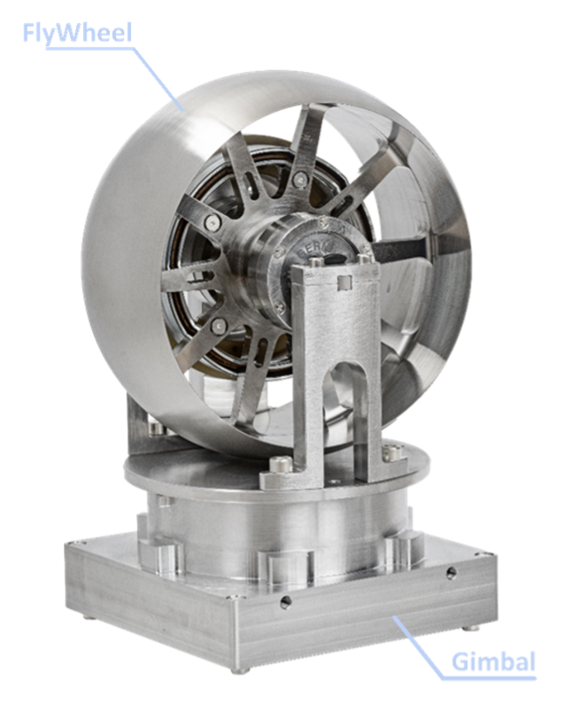
A Control Moment Gyroscope (CMG) is an attitude control unit consisting of a spinning wheel, and one or more motorized gimbals. The purpose of these gimbals is to change the wheel’s axis of rotation in a controlled way.
As a gimbal moves, it forces the spinning wheel to change its axis, which produces gyroscopic torques. These torques can then be used to control the orientation of a spacecraft.
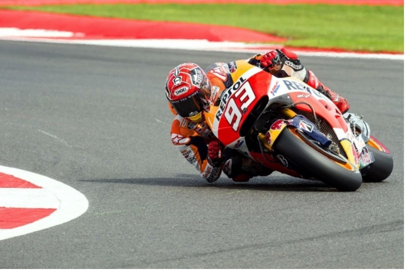
An example of this effect is what is experienced by motorcyclists when they need to take a turn. The front wheel of the motorbike is spinning fast, like the wheel of a CMG, and the handle bar is a gimbal. When the driver turns the wheel, gyroscopic torques are produced that make the bike lean on its side.
It is important to highlight here that the effort (torque) the pilot needs to make to turn the handle bar is much smaller than what is needed to make the bike lean. If you need convincing, just consider that at the end of the turn, the driver slightly rotates the handle bar in the opposite direction, and the bike comes back to a vertical position. This shows that a bike weighing hundreds of kilograms can be lifted from the ground by the slight rotation of the handle bar, that’s the incredible power of CMGs.
Click Order button next to the service you want to purchase and leave your contacts in a follow-up form. We will get in touch with you shortly to clarify all the details.
Control moment gyroscopes and reaction wheels are both used to provide torque, and both use flywheels to do so. The big difference between them is the way they use their flywheels to deliver these torques.
In reaction wheels, torques are obtained by varying the speed of the flywheel, while in CMGs torques are obtained by varying the direction of the flywheel’s axis of rotation while maintaining a constant flywheel speed.
Reaction wheels suffer from two important limitations which physically restrict the amount of torque and momentum they can provide.
First of all, as their flywheel speed increases, the power required to deliver a given torque increases as well, which makes them relatively inefficient.
Secondly, even if power could be supplied, the mechanical stress in the flywheel increases with the square of its angular speed. This means that there is a physical limit beyond which the stress is so high that the flywheel can literally not hold itself together anymore.
CMGs on the other hand operate their flywheel at constant speed, which means they do not suffer from these limitations. The axis of rotation of the wheel can be changed in a matter of seconds, which means that momentum can be delivered much faster than it would with reaction wheels.
One aspect where reaction wheels do potentially hold an advantage over CMGs is for very small manoeuvres. This is due to the fact that the torque output of a CMG is related to the gimbal speed, whereas the torque output of a reaction wheel is related to the electrical current in it’s motor. Changing the value of an electrical current is naturally faster than changing the speed of a mechanical object. Fast torque variations are consequently easier to achieve with reaction wheels than they are with CMGs.
In-Orbit Agility is defined as the capability of a satellite to change its orientation rapidly or in physical terms as the amount of torque capabilities that the satellite has. For the same satellite, doubling the torque will simply double the speed at which the satellite can be put into motion. Torque is for rotation what the “thrust” is for translation. Offering 10x more agility to satellite thus means having 10x more torque capabilities.
In the numbers, let us assume that a satellite is required to perform a 60-degree maneuver to orient its payload from 30 degrees backward looking to 30-degree forward looking. This maneuver is typical in high agility imaging modes when a satellite finishes imaging a zone of interest and switches to another zone. To demonstrate how torque and thus CMG helps improving the agility and performing such maneuver, the following hypotheses are listed
Satellite mass is 100 kg
Satellite moment of inertia is 10 kgm²
Momentum capacity of the attitude control system = 1.8 Nms
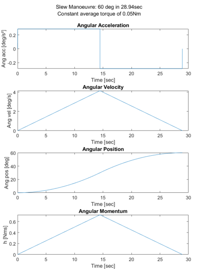
In a first scenario, (case A) the satellite has been equipped with state-of the-art reaction wheels offering a constant average torque capability up to 0.05 Nm (Sinclair interplanetary RW3-1.0). The maneuver is performed in 29 seconds. The profile goes as depicted below.
Manoeuvre profile for a 60 deg manoeuvre made by 100 kg satellite equipped with reaction wheels (50 mNm of average torque) and having with 4RW a total momentum capacity of 1.8 Nms. Because of the low torque capabilities of reaction wheels, one can see that the satellite never reaches its maximum momentum capacity.
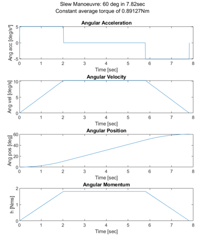
In a second scenario (Case B), the satellite has been equipped with CMG, offering a constant average torque capability up to 0.89 Nm. The maneuver is performed in 7.8 seconds, or an improvement of almost x4. The profile goes as depicted below.
Manoeuvre profile for a 60 deg manoeuvre made by 100 kg satellite equipped with VEO’s product (900 mNm of average torque) and having a total momentum capacity of 1.8 Nms. Thanks to the high torque, the satellite is rapidly put in motion, reaches its cruise slew speed (10 deg/s) and then decelerates.
Spacecraft are subject to disturbances from the environment, which need to be compensated for by the momentum exchange devices. This external source of momentum is therefore being accumulated on the spacecraft, which can lead the momentum devices to reach their maximum capacity. This phenomenon is called saturation, and needs to be handled carefully.
Saturation can happen both for Reaction Wheels and Control Moment Gyroscopes, but can be avoided altogether by proper mission planning.
In order to avoid saturation, momentum needs to be extracted from the spacecraft at regular intervals by a procedure usually referred to as ‘momentum dumping’. By far the most common method to do so for Earth orbiting satellite is to make use of the Earth’s magnetic field. Torques can be produced on the spacecraft by means of electromagnets, in such a way that the total spacecraft momentum is decreased. These electromagnets are commonly known as ‘magnetic torquers’, or ‘magnetorquers’.
Momentum dumping can impact the pointing performances of a spacecraft, as it represents an added disturbance. However, this disturbance can be minimized by adequate sizing of the momentum exchange devices and the magnetic torquers. These momentum dumping events can (and should) be scheduled when it is least impacting the mission.
VEOWARE Control Moment Gyroscopes
Every day, satellites provide geospatial insights, orbital situational awareness and relay information for users, analysts, and decision makers to best position their business & government in the present very rapidly changing geopolitical & commercial environment.
To accomplish their mission, satellites need to control their orientation and manoeuvre to point towards selected targets on the Earth’s surface (for instance to collect imagery or to do telecommunication) or in space for situational awareness. Satellite on-board agility (= ability to manoeuvre) is a key measure of satellite effectiveness.
Today, 99% of satellites use Reaction Wheels (RW) to enable their agility. Reaction wheels come in all sizes, so are suitable for small satellites, but provide limited speed to the rotation of satellites. More performing actuators exist, namely the Control Moment Gyroscopes (CMG). Used by only 1% of the satellite market they are mostly US built & integrated on US Defence satellites. These CMGs are bulky, high cost, have lengthy production times, and are ITAR restricted, leaving non-US industry almost completely locked out of this technology. VEOWARE proposes affordable ITAR-free CMGs tailored for small satellites with a short lead-time.
VEOCMGs enable rapid re-targeting and collection of more imagery which for the satellite operators means enabling more revenue opportunities and shorter response time (i.e. more data delivered faster)
On one hand, a gain in agility enables Earth Observation satellites to analyze more zones of interest & please more customers. In-orbit agility also enable them to spend more time downlinking data as they can benefit from any opportunity to communite with ground stations, enabling shorter response time for decision makers.
On the other hand, such gain in performance will enable satellite operators to double (up to triple) their revenue as they will be able to reorient their satellite faster, analyze zones that are not shaded by clouds, & downlink the required data more often.
Additionally, state-of-the-art satellite imaging strategies are only possible thanks to the use of VEOCMGs, namely the mapping target imaging and the multi-point target imaging. Such imaging strategies lead to diversification of downstream applications due to the fact that more quality data would be available on the market.
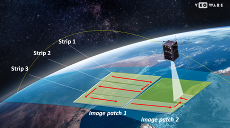
MAPPING TARGET IMAGING
Independently of the type of sensor (2D or line sensor) used for the payload, VEOCMGs un-lock the ability of the satellite to perform a truly effective imagery collection pattern referred as “multi-strip” collection.
Such pattern consists of multiple strips collected by the sensor one after the other. Each strip can be collected by multiple images in the case of 2D sensor or a single acquisition in case of a line sensor in push broom or Time-Delay Integration (TDI) mode. By stitching the strips together, a larger image patch is collected in a single satellite pass.
Equipped with VEOCMGs, a 300kg satellite would be able to perform Surveillance on Areas of Interest as large as 50km x 50km in a single pass. Without VEOCMG, the scene is limited to 10km x 50km.
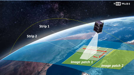
Figures below depict how the collection of each image patch is proposed thanks to the agility provided by VEOCMGs. Top figure illustrates the line sensor case while the bottom figure illustrates the 2D sensor scenario.
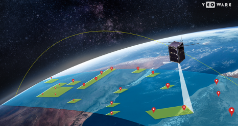
MULTI-POINT TARGET IMAGING
During the cold war, satellites have been built to perform Intelligence, Surveillance and Reconnaissance (ISR) missions. In other words, they were designed to look at identified targets on the ground. Maximizing the ability to collect a large number of important targets was and remains crucial today for military but also non-military applications. Satellite constellations (low resolution) can detect change daily but higher resolution satellites can then be tasked to collect detailed information where such change occurred. VEOCMGs un-lock the true potential of satellite, increasing their effectiveness in perform such operations.
This strategy is referred as “multi-point target” collection and exploits the ability of VEOCMGs to deliver large torques for a given momentum, stabilize rapidly and offer fine pointing.
A 50kg satellite equipped with VEOCMGs is able to quickly maneuver in pitch, roll, yaw, or a combination of those to point to an area of interest, collect up to 4x more images (e.g. for airfield activity monitoring, conflict detections, etc.) than without VEOCMGs, and move on.
This imaging mode is also essential for cloud avoidance, where the satellite is able to collect imagery only where the minimum cloud cover is located. Such scenario is illustrated in the figure below.
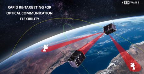
VEOCMGs enable rapid re-targeting and fine stable pointing, allowing the satellite equipped with such technology to effectively choose their optical communication strategy to maximize the resilience.
Satellite to Satellite rapid switch when visibility is lost, link too weak, or assets is compromised
Ground station to Ground station when cloud coverage increases, or assets is compromised
In addition, VEOCMGs enable more frequent use of ground stations, which results in more data transfer and more flexibility in satellite operations.
Equipped with VEOCMG, a typical 100kg satellite would be able to rapidly switch from normal operation to direct optical downlink but also to rapidly change from one optical ground station to another for cloud avoidance or simply to maximize the data transfer performance.
Taking less than 10 seconds instead of 30 seconds without VEOCMG, the satellite would be able to receive, relay or downlink encrypted data with 3x more ground optical terminal in a single pass, offering a significant boost in the communication resilience.
In addition, CMGs are known to operate at a constant speed versus reaction wheels that always see their speed vary over time as the spacecraft is operated. CMGs thus offer a unique intrinsic benefit on micro-vibration management.
The benefit using CMG for laser communication is dual.
CMGs offer the lowest micro-vibration. The speed of the wheel of a CMG can be tuned / chosen so that it offers the best micro-vibration environment (i.e. lowest possible) to the satellite and its laser terminals hence lowering the cost of the laser gimbal technology
CMGs thus bring inherent redundancy. The CMG could replace the function of the laser terminal gimbal (should it fail) and actually quickly re-target the full satellite so that it can still operate.
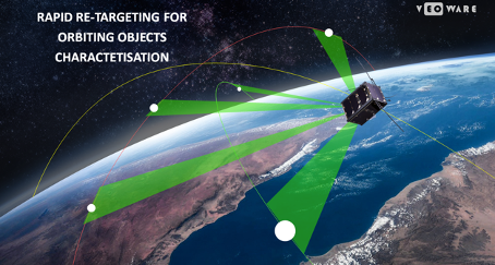
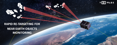
VEOCMGs enables further understanding the mission, capability, health status and intent of objects placed in orbit as they increase the amount of third-party satellites or objects that can be analyzed. Satellite will be able to cover each portion of the sky more efficiently and more effectively.
Equipped with VEOCMG, a 150kg Space Situation Awareness satellite would be able evaluate more than x3 more space objects over the same duration than without VEOCMGs, significantly increasing the level of intelligence on potential threats and reducing the time to action (if required). This includes:
More third-party satellite behavior characterization per day
More assessments for potential threats from debris or inactive satellites per day
More Near-Earth Objects (NEO) imaged & characterized per day
Figures below depict a few scenarios where VEOCMGs can be exploited.